
āVāŖü[āYüEāŖāAāNā^āōāXüEā}ābā`āōāOé╔é┬éóé─źźźARRL HANDBOOKéµéĶ(Sep 23. 2014)
āvāīü[āgē±śHé®éń50āČĢēēūéųā}ābā`āōāO(É«Źć)ééŲéķÅĻŹćüAHFé┼é═ÅWÆåÆĶÉö(LźC)é╔éµéķā╬ā}ābā`éŌĢ└Ś±ŗżÉUÆ╝Ś±ŗŗōd(āŖāōāNāRāCāŗ)Ģ¹Ä«é¬łĻö╩ōIéŠüB
éĄé®éĄüA144MHzéŌ430MHzæčé╔é╚éķéŲé▒é╠Ģ¹¢@é┼é═āvāīü[āgÅoŚ═CéŌāXāgāīü[CŗyéčāXāgāīü[Lé¬ī°é½üA¢┌ōIijögÉöé┼łĻÆĶé╠ĢēēūÆ’ŹRÆléŖmĢ█éĄéĮŗżÉUéōŠéķé╠é═Źóō’é╔ōÖéĄéóüB
é╗é▒é┼ɳśHÆĘ(ōdŗCÆĘā╔/4źā?2)錜ŚpéĄéĮŗżÉUē±śHéüAāvāīü[āgÅoŚ═CéŌāXāgāīü[CéŖ▄é▀é─Ź\ɼéĘéķĢ¹¢@鬏╠Śpé│éĻéķéµéżé╔é╚é┴éĮüB
é╗éĄé─üAö„żCé╔éµéķāvāīü[āgō»Æ▓éŲüAō»Ślé╔ö„żCé╔éµéķāvāīü[āgé®éńé╠ĢēēūīŗŹćéŹséżÄĶ¢@é¬Ģ╣Śpé│éĻé─éóéķüB
ARRL HANDBOOKé╔é═ī├éŁé®éńé╗é╠ēÉÓ鬏séĒéĻé─éóéĮé¬üAŹ┼ÉVé╠2014öNö┼éī®éķéŲé╗é╠ŗLÅq鬢│éŁé╚é┴é─éóéķüB
éóé▄é│éńÉ^ŗ¾ŖŪé╚é±é─źźźéŲéĘéķÉ║é¬ĢĘé▒é”é─é½é╗éżéŠé¬üAÉ«ŹćéŚØēéĘéķéĮé▀é╠āeāNājābāNé╠łĻé┬éŲéĄé─Æmé┴é─é©éóé─æ╣é═¢│éóüB
ā|āCāōāgé═CźR(50āČ)é╠Æ╝Ś±ē±śHéĢ└Ś±ē±śHé╔ōÖē┐ĢŽŖĘéĄé─ĵéĶłĄéżÅłé╔éĀéķüBZ=Rü}Xé╠Æ╝Ś±ē±śHé╠é▌é╔ŹSé┴é─éóéķéŲé▒é╠üuāVāŖü[āYźāŖāAāNā^āōāXźā}ābā`āōāOüvé╠ŚØēé╔é═ÆHéĶé┬é»é╚éóüB
ł╚ē║é╔ARRL HANDBOOK 2006é╠Chapter 18é®éńé╠ö▓Éłéé▄éŲé▀é─é▌éĮüBé▒é▒é┼é═144MHzéŚßé╔ÉÓ¢ŠéĄé─éóéķüB
ÄQŹlÅŅĢ±üFDaycounter,Incé╠āTāCāgé╔Æ╝Ś±-Ģ└Ś±ĢŽŖĘāJāŖāLāģāīü[ā^é¬éĀéķé╠é┼ĢųŚśéŠüBŚßé”é╬Æ╝Ś±CéŲ50āČé╠Æ╝Ś±ē±śHé╠āCāōāsü[ā_āōāXé¬145MHzé┼ōÖē┐é╔é╚éķĢ└Ś±ē±śHé╠ÆĶÉöéÅuÄ×é╔īvÄZéĄé─éŁéĻéķüB
é╚é©üAō¢æRé╚é¬éńĢ└Ś±ē±śHé┼éÓ-jXɼĢ¬é¬æČŹ▌éĘéķé╠é┼üAé▒éĻé═āvāīü[āgō»Æ▓CéŌɳśHÆĘōÖéŲé╠īōé╦Źćéóé┼āLāāāōāZāŗéĘéķé▒éŲé╔é╚éķüB
ō»Äąé╠āTāCāgé╔é═é╗é╠æ╝ĢųŚśé╚āJāŖāLāģāīü[ā^é╠ł─ōÓé¬æĮÉöéĀéķé╠é┼ŚLī°ŚśŚpéĘéķéŲŚŪéóüB
āXā~āXā`āāü[āgā\ātāgé┼Rs-jXséāvāŹābāgéĄé─é®éńĢ\Ä”éāAāhā~ābā^āōāXā`āāü[āgé╔Éžæųé”üAé╗é╠Ģ\Ä”Ælé®éńRpéŲXpéōŪé▌ÆĶÉöéīvÄZéĘéķĢ¹¢@éÓéĀéķé¬üAé▒é╠āJāŖāLāģāīü[ā^éÄgé”é╬łĻÅué╔éĄé╗é╠ŹņŗŲ鬏sé”üAö„Æ▓É«éÓÅuÄ×é╔éĄé─Źsé”éķüB
From THE ARRL HANDBOOK 2006 Chapter 18 ügRF Power Amplifiresüh
 TANK OUTPUT CIRCUITS
Tank circuit output networks need not take the form of a capacitor connected in parallel with an inductor. A number of equivalent circuits can be used to match the impedances normally encountered in a power amplifier. Most are operationally more flexible than a parallel-resonant tank. Each has its advantages and disadvantages for specific applications, but the final choice usually is based on practical construction considerations and the component values needed to implement a particular network. Some networks may
require unreasonably high or low inductance or capacitance values. In that case, use another network, or a different value of QL. Several different networks may be investigated before an acceptable final design is reached.
The impedances of RF components and amplifying devices frequently are given in terms of a parallel combination of a resistance and a reactance, although it is often easier to use a series R-X combination
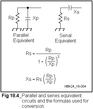
to design networks. Fortunately, there is a series impedance equivalent to every parallel impedance and vice versa. The equivalent circuits, and equations for conversion from one to the other, are given in
Fig 18.4. In order to use most readily available design equations for computing matching networks, the parallel impedance must first be converted to its equivalent series form.
The QL of a parallel impedance can be derived from the series form as well. Substitution of the usual formula for calculating QL into the equations from Fig 18.4 gives
ü@QL = Rp/Xp (12)
where
ü@Rp = the parallel equivalent resistance
ü@Xp = the parallel equivalent reactance
DESIGN EXAMPLE 2 : A MEDIUMü@POWERü@144MHz AMPLIFIER
For decades the 4CX250 family of power tetrodes has been used successfully up through 500 MHz. They are relatively inexpensive, produce high gain and lend themselves to relatively simple amplifier designs. In amateur service at VHF, the 4CX250 is an attractive choice for an amplifier. Most VHF exciters used now
by amateurs are solid state and often develop 10 W or less output. The drive requirement for the 4CX250 in grounded cathode, Class AB operation ranges between 2 and 8 W for full power output, depending on frequency. At 144 MHz, manufacturerüfs specifications suggest an available output power of over 300 W.
This is clearly a substantial improvement over 10 W, so a 4CX250B will be used in this amplifier.
The first design step is the same as in the previous example: Verify that the proposed tube will perform as desired while staying within the manufacturerüfs ratings.
Again assuming a basic amplifier efficiency of 60% for Class AB operation, 300 W of output requires a plate input power of 500 W. Tube dissipation is rated at 250 W, so plate dissipation is not a problem,
as the tube will only be dissipating 200 W in this amplifier. If the recommended maximum plate potential of
2000 V is used, the plate current for 500 W input will be 250 mA, which is within the manufacturerüfs ratings. The plate load resistance can now be calculated. Using the same formula as before, the value is determinedto be 5333āČ.
The next step is to investigate the outputü@circuit. The manufacturerüfs specificationü@for COUT is 4.7 pF. The inevitableü@circuit strays along with the tuning capacitorü@add to the circuit capacitance. Aü@carefully built amplifier might only haveü@7 pF of stray capacitance, and a speciallyü@made tuning capacitor can be fabricated toü@have a midrange value of 3 pF. The totalü@circuit capacitance adds up to about 15 pF.
At 144 MHz this represents a capacitiveü@reactance of only 74āČ. The QL of a tankcircuit with this reactance with a plate loadü@resistance of 5333āČ?is 5333/74 = 72. A piü@output matching network would be totallyü@impractical, because the L required wouldü@be extremely small and circuit lossesü@would be prohibitive. The simplest solutionü@is to connect an inductor in parallelü@with the circuit capacitance to form aü@parallel-resonant tank circuit.
To keep tank circuit losses low withü@such a high QL, an inductor with very highü@unloaded Q must be used. The lowest-lossü@inductors are formed from transmissionlineü@sections. These can take the form ofü@either coaxial lines or strip lines. Bothü@have their advantages and disadvantages,ü@but the strip line is so much easier to fabricateü@that it is almost exclusively used inü@VHF tank circuits today.
The reactance of a terminated transmissionü@line section is a function of both itsü@characteristic impedance and its lengthü@(see the Transmission Lines chapter).
The reactance of a line terminated in aü@short circuit isü@
ü@Xin = Zo tan l (46)
where
ü@Xin = is the circuit reactance.
ü@Zo = the lineüfs characteristic impedance
ü@l = the transmission line length in degrees
For lines shorter than a quarterü@wavelength (90üŗ) the circuit reactance isü@inductive. In order to resonate with theü@tank-circuit capacitive reactance, theü@transmission-line reactance must be theü@same value, but inductive. Examination ofü@the formula for transmission-line circuitü@reactance suggests that a wide range ofü@lengths can yield the same inductiveü@reactance, so long as the line Zo is appropriatelyü@scaled. Based on circuit Q considerations,ü@the best bandwidth for a tankü@circuit results when the ratio of Zo to XINü@is between one and two. This implies thatü@transmission line lengths between 26.5üŗand 45üŗgive the best bandwidth. Betweenü@these two limits, and with some adjustmentü@of Zo, practical transmission linesü@can be designed. A transmission-lineü@length of 35üŗ is 8 inches long at 144 MHz,ü@a workable dimension mechanically. Substitutionü@of this value into the transmission-line equation gives a Zo of 105āČ.
The width of the strip line and its placementü@relative to the ground planes determineü@the line impedance. Other strayü@capacitances such as mounting standoffsü@also affect the impedance. Accurate calculation
of the line impedance for mostü@physical configurations requires extensiveü@application of Maxwellüfs equationsü@and is beyond the scope of this book. Theü@specialized case in which the strip line isü@parallel to and located halfway betweenü@two ground planes has been documentedü@in Reference Data for Radioü@Engineersü@(see Bibliography). According to chartsü@presented in that book, a 105-āČ?strip lineü@impedance is obtained by placing a lineü@with a width of approximately 0.4 timesü@the ground plane separation halfway betweenü@the ground planes. Assuming theü@use of a standard 3-inch-deep chassis forü@the plateü@compartment, this yields a striplineü@width of 1.2 inches. A strip line 1.2ü@inches wide located 1.5 inches aboveü@the chassis floor and grounded at oneü@end has an inductive reactance of 74āČ?atü@144 MHz.
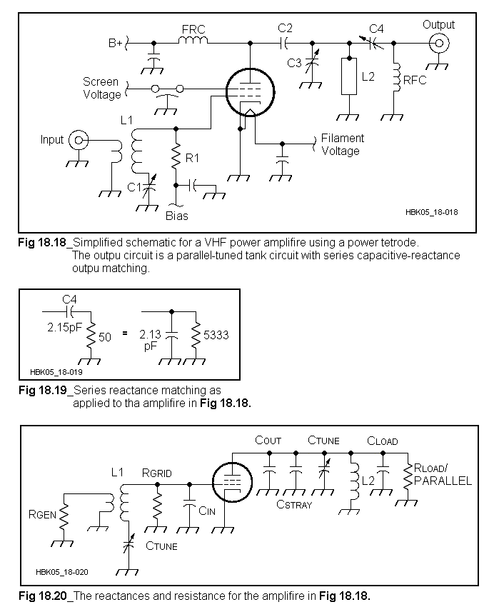
The resulting amplifier schematic diagramü@is shown in Fig 18.18. L2 is the striplineü@inductance just described. C3 is theü@tuning capacitor, made from two parallelü@brass plates whose spacing is adjustable.
One plate is connected directly to the stripü@line while the other is connected to groundü@through a wide, low-inductance strap. C2ü@is the plate blocking capacitor. This can beü@either a ceramic doorknob capacitor suchü@as the Centralab 850 series or a homemadeü@ügTeflon sandwich.üh Both are equally effectiveü@at 144 MHz.
Impedance matching from the plateü@resistance down to 50āČ?can be eitherü@through an inductive link or throughü@capacitive reactance matching. Mechanically,ü@the capacitive approach is simplerü@to implement. Fig 18.19 shows the developmentü@of reactance matching through aü@series capacitor (C4 in Fig 18.19). By
using the parallel equivalent of the capacitorü@in series with the 50āČ?load, theü@load resistance can be transformed to theü@5333āČ?plate resistance. Substitution ofü@the known values into the parallel-toseries
equivalence formulas reveals that aü@2.15 pF capacitor at C4 matches the 50āČü@load to the plate resistance. The resultingü@parallel equivalent for the load is 5333āČü@in parallel with 2.13 pF. The 2.13-pF
capacitor is effectively in parallel with theü@tank circuit.
A new plate line length must now beü@calculated to allow for the additionalü@capacitance. The equivalent circuit diagramü@containing all the various reactancesü@is shown in Fig 18.20. The total circuit capacitance is now just over 17 pF, whichü@is a reactance of 64āČ. Keeping the striplineü@width and thus its impedance constantü@at 105āČ?dictates a new resonant line length of 31üŗ. This calculates to be 7.14 inches for 144 MHz.
The alternative coupling scheme isü@through the use of an inductive link. Theü@link can be either tuned or untuned. Theü@length of the link can be estimated basedü@on the amplifier output impedance, in thisü@case, 50āČ. For an untuned link, the inductiveü@reactance of the link itself should beü@approximately equal to the output impedance,ü@50āČ. For a tuned link, the lengthü@depends on the link loaded Q, QL. The linkü@QL should generally be greater than two,ü@but usually less than five. For a QL of threeü@this implies a capacitive reactance ofü@150āČ, which at 144 MHz is just over 7 pF.

The self-inductance of the link should ofü@course be such that its impedance atü@144 MHz is 150āČ?(0.166 mH). Adjustmentü@of the link placement determines theü@transformation ratio of the circuit line. Some fine adjustment of this parameterü@can be made through adjustment of the linkü@series tuning capacitor. Placement of theü@link relative to the plate inductor is anü@empirical process.
The input circuit is shown in Figs 18.21ü@and 18.23. CIN is specified to be 18.5 pF forü@the 4CX250. This is only ?j 60āČ?atü@2 m, so the pi network again is unsuitable.
Since a surplus of drive is available with aü@10 W exciter, circuit losses at the amplifierü@input are not as important as at the output.
An old-fashioned ügsplit-statorüh tuned inputü@can be used. L1 in Fig 18.18 is series tunedü@by CIN and C1. The two capacitors areü@effectively in series (through the groundü@return). A 20-pF variable at C1 set to
18.5 pF gives an effective circuit capacitanceü@of 9.25 pF. This will resonate atü@144 MHz with an inductance of 0.13 ?H atü@L1. L1 can be wound on a toroid core forü@mechanical convenience. Theü@50āČ?inputü@impedance is then matched by link couplingü@to the toroid. The grid impedance isprimarily determined by the value for R1,ü@the grid bias feed resistor.


