![]()
![]()
![]()
![]()
hübner/ESU #4070 decoder for Railbus VT98
and
Circuit diagram of Railbus VT98
The directions appears in this document is:
Both for VT98 and VS98
 (Top View)
Pin assign of decoder.
Combination of 'direction arrow' on 6021 CU and output.
Direction |
#8 MOTOR + |
#4 MOTOR - |
#12 Lf |
#7 Lr |
/\ |
Plus |
Minus |
ON |
OFF |
\/ |
Minus |
Plus |
OFF |
ON |
*Voltages are not measured in actual circuit. Logically analyzed.
Circuit diagram of Hübner's railbus VT98.
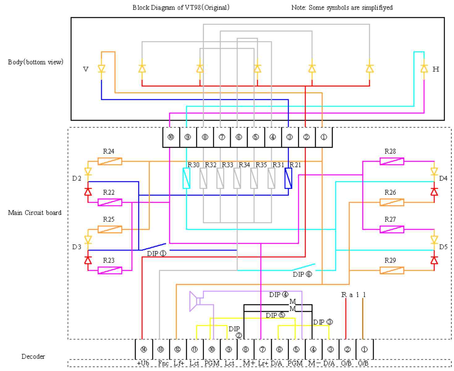 Please click on image to enlarge it.
![]()
![]()
![]()
Copyright © 2000 by Jun Maeda / KOBE JAPAN