![]()
![]()
![]()
![]()
märklin #600401 MAXI-Delta decoder for BR140
This is a result of my study for #600401 MAXI-Delta decoder for BR140.
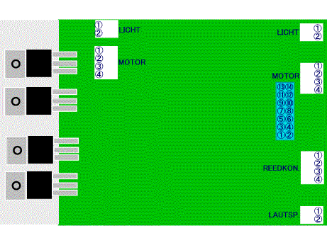
Pin assign of connectors on the decoder are:
<LICHT> - both connector are connected in parallel.
<MOTOR> - both connector are connected in parallel.
<Blue connector> - for #56560 sound circuit.
<REEDKON.> - connector for reedswitches.
If #1-#2 short, Horn function activate. If #3-#4 short Horn pitch is high.
<LAUTSP.>
Combination of 'direction arrow' on 6021 CU and output.
Direction |
<MOTOR>#2 |
<MOTOR>#3 |
<LICHT>#1 |
<LICHT>#2 |
/\ |
+0~ +20V |
0V |
+0~+20V |
0V |
\/ |
0V |
+0V~+20V |
0V |
+0~+20V |
All voltages are measured between internal ground.
Voltages of <LICHT> is depends on voltage of <MOTOR>.
![]()
![]()
![]()
Copyright © 2000 by Jun Maeda / KOBE JAPAN