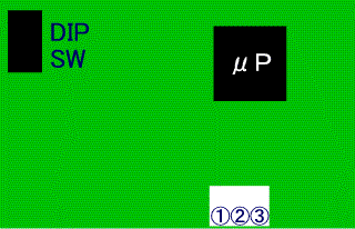
märklin #601356 decoder for BR91.3(T9.3)
and
märklin #601355 Sound effect circuit for BR91.3(T9.3)
This is a result of my study for märklin #601356 decoder for BR91.3(T9.3) and märklin #601355 Sound effect circuit for BR91.3(T9.3).
Special note of this Decoder and Sound effect circuit!
märklin #601356 decoder for BR91.3(T9.3)
Pin assign of terminals and pin headers on the decoder are:
Pin# Description Specification Color of wire #1
TELEX
Switched to GND by additional circuit board with about 10s 'egg timer'
#2 +Ub +20V #3 #4 Lr +16.4V(Switched by Lr to GND with series 1k ohm resister)
Pin#
Description
Specification
Color of wire
#1
Motor
See below chart
#2
Motor
See below chart
#3
Current Pickup
From insulated wheel
#4
Combination of 'direction arrow' on 6021 CU and output.
Direction
<MOTOR>#1
<MOTOR>#2
/\
+0~ +18V
0V
\/
0V
+0V~+18V
Pin# Description Specification Color of wire #1
Lf
+16.4V(Switched by Lf to GND with series 1k ohm resister)
#2 +Ub +20V #3 +Ub +20V #4 Smoke +16.4V(Switched by f1 to GND)
Pin#
Description
Color of wire
#1
Speaker
#2
Speaker
Pin# Description Specification #1
Rail
From current pickups #2 Rail From chassis #3 GND #4 GND(?)
Pin# Description Specification #1
TELEX
+5V Output of Egg timer(about 10second) #2 N.C. #3 F4 Pull down to GND when F4 turned on #4 Lf / Lr Pull down to GND when Function turned on (both Lf / Lr) #5
F3
Pull down to GND when F3 turned on
#6
Direction
/\ =+5V \/ =GND
#7
F2
Pull down to GND when F2 turned on
#8
N.C.
#9
Steam Sound
Pull down to GND by two position sliding switch on decoder PCB turned on
#10
Full speed voltage(?)
Reference voltage for measuring speed step +2.4V(=Speed step 14)
Pin# Description Specification #1
Direction change acknowledge(?)
Normal= 2.5V Direction change = About -20V one Pulse
#2
Direction change acknowledge(?)
Normal= 2.5V Direction change = About -20V one Pulse
#3
Ordered Speed step*
(Directly according to speed step ordered by control unit)
#4
Actual motor speed*
(According to Actual motor voltage including accelaration / brake delay)
*These speed signals are according to new 27 speed step system.
Value for each 0.5 step is about 75mV(may vary in both lower and top speed step). Value of full speed step is 2.4V.
<About 27 speed step system>:
888Refer for märklin magazin 2/2000 'Geschwindigkeits-Feinregelung mit 27 Fahrsufen' .
Pin# Description Specification #1
Speaker
From sound effect circuit #2
Speaker
From sound effect circuit
Three position Switch under side of circuit.
Usage: Track Voltage Select.
Front Center Rear DC AC(Analog)
DIGITAL
Two position Switch under side of circuit.
Usage: Chuff sound control
Front Rear ON OFF
This switch does not cut off both Steam Bell and Whistle sound.
These sounds are able to digitally control any time as long as the loco on the digital track and DIP switch #2 of #601355 is ON.
märklin #601355 Sound effect circuit for BR91.3(T9.3)

Pin assign of terminal to be connected hall sensor unit #602178:
Pin#
Description
Specification Color of wire
#1
Vcc
+5V
#2
Signal
Vcc when hall sensor is turned on. Other wise GND
#3
GND
GND
Usage of DIP switch:
Switch# ON
OFF
#1
Not used(?) Not used(?) #2
Bell and Whistle ON Bell and Whistle OFF #3
Automatic turnoff after 50 seconds Background Noise #4
Automatic fireman shoveling coal No shoveling sound. #5
Not used(?) Not used(?) #6
Flat valve set noise Round valve set noise #7
Coasting control on. Always full chuff sound #8
Four chuffs per one wheel round Two chuffs per one wheel round
- All of name and number of connectors or terminals are not official name / number of märklin.
- All of Voltage are measured between rectifier(internal) Ground(=Gnd).
Copyright © 2001 by Jun Maeda / KOBE JAPAN