


Simple
digital turnout receiver with c80 decoder.
This is
a development of digital turnout receiver with c80 HO locomotive
decoder.
Basic concept:
- This unit developed for temporary
layout.
- Very simple for hook up. Just put
in the turnout with this receiver in temp. layout.
- No additional equipment is
required more than #6021 control unit.
Comparison with k83
turnout decoder:
- #6040 Keyboard is not required.
- No long three-line wirings from
decoder are not required.
- The turnout can be set up at any
point of the layout with out wiring.
How does it works?:
- Setup:
- Put the turnout on the
site that you want to put in.
- Connect two wires(Red/
Brown) to appropriate rail.
- Operation(on #6021):
- Call the address that set
on c80 decoder.
- Push 'off' button up to
one second.
- The lead rail moves
opposite position.
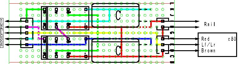
Circuit:
Bottom view of circuit board.
Click the image for clearer drawing.
The dotted lines are jump wire on upper side of the circuit
board.
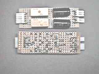
Bottom view of relay.
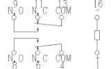
Relay: Matsushita(NAiS) :DS2E-M-DC24V, Condenser: 470uF / 50V
Sequence of circuit:
- The Lf/Lr of c80 pull down to ground(=push
'off' button).
- One of condenser('C') become charged by
current thru micro switch in turnout mechanism #5625. The
current for coil of #5625 still interrupt by relay
contact NO(normally open).
- When the charge of 'C' completed, the coil
of relay magnetized.
- The current for opposite coil from
existing position of turnout mechanism #5625 turned on by
relay contact NO(normally open). Simultaneously, another
coil of #5625 is shut down by relay contact NC(normally
close).
- When the lead rail have moved to another
position, the current for coil of #5625 is cut off. In
this phase opposite coil is simultaneously connected to
power source, but relay keeps former position by means of
charge of condenser. So the turnout mechanism does not
chatter from one side to another side.
- If c80 turned off during charge of
condenser is remaining, The lead rail stays at the
position.
- After charge of condenser lasted, the
circuit waiting for next pulse from c80.
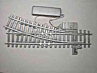
Fitting to the box.
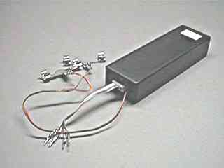
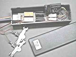
- The circuit and c80 installed in
small box.
- Two wires with track clip #56031
clip to two rails.
- Five wires connect to terminal of
#5625 turnout mechanism(1-4 and L).
-


Copyright ©
2000 by Jun Maeda / KOBE JAPAN