![]()
![]()
![]()
![]()
Difference of #658530 MAXI Delta and #60955 decoder.
(and problem comes from the difference.)
The #60955 MAXI high efficiency decoder has very high potential. So it is good idea to change the decoder from #658530 Delta to #60955, but there is a complicated problem comes from difference of these two decoders.
What's differ?
Please notice for the polarity of each outputs.
Relationship of 'direction arrow' on 6021 CU and pin outputs.
#658530 (Delta):
Direction |
#3(motor) |
#1(Lr) |
#8(Lf) |
/\ |
+0~ +20V |
0V |
+0~+20V |
\/ |
-0~ -20V |
-0V~-20V |
0V |
#4~#6 always connected to internal gnd.(0V).
#60955(high eff. digital):
| Direction | #3(motor) | #6(motor) | #1(Lr) | #8(Lf) |
/\ |
+0~+20V |
Gnd |
off |
Gnd |
\/ |
Gnd |
+0~+20V |
Gnd |
off |
All voltages are measured between internal ground.
What's problem?
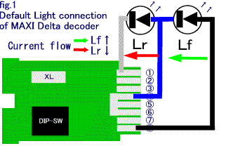
Before exchange of decoder:
I think this configurations by means of:
BUT, this simplification makes problem.
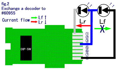
After exchange a decoder to #60955:
This is a 'Head lights problem' occured by changing decoder.
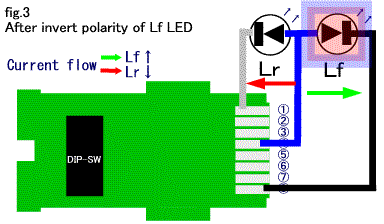
How to fix?
Invert the polarity of Lf LED.
Simply doing this solves the problem.
I didn't test this configuration on DC= rails. I'll test it and report what happen in that situation in near future.
But I think there are many variations in certain models(as always in marklin's products).
Make sure, take a look your model for detail and think well actual diagram, before trying to do this. As a fact, I've burned out four yellow LEDs of E69 when I faced on this problem!
Be care full all the time, you dissect your models.
NOTE:The circuit diagrams fig.1,2 and 3 are simplified drawings. Naturally there are resister etc. in actual circuit.
![]()
![]()
![]()
Copyright © 2000 by Jun Maeda / KOBE JAPAN