![]()
![]()
![]()
![]()
hübner 1400/1405 decoder for Railbus VT98/VS98(VB98)
and
Circuit diagram of Railbus VT98 and VS98
The directions appears in this document is:
Both for VT98 and VS98
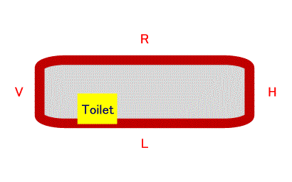 (Top View)
Pin assign of decoder. (Applies to both 1400 and 1405)
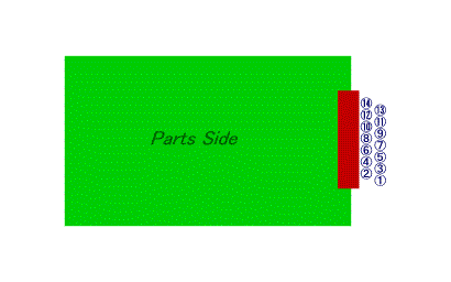
* Not connected in 1405 decoder.
Combination of 'direction arrow' on 6021 CU and output.
Direction |
#8 MOTOR + |
#4 MOTOR - |
#12 Lf |
#7 Lr |
/\ |
Plus |
Minus |
ON |
OFF |
\/ |
Minus |
Plus |
OFF |
ON |
*Voltages are not measured in actual circuit. Logically analyzed.
Circuit diagram of Hübner's railbus VT98.
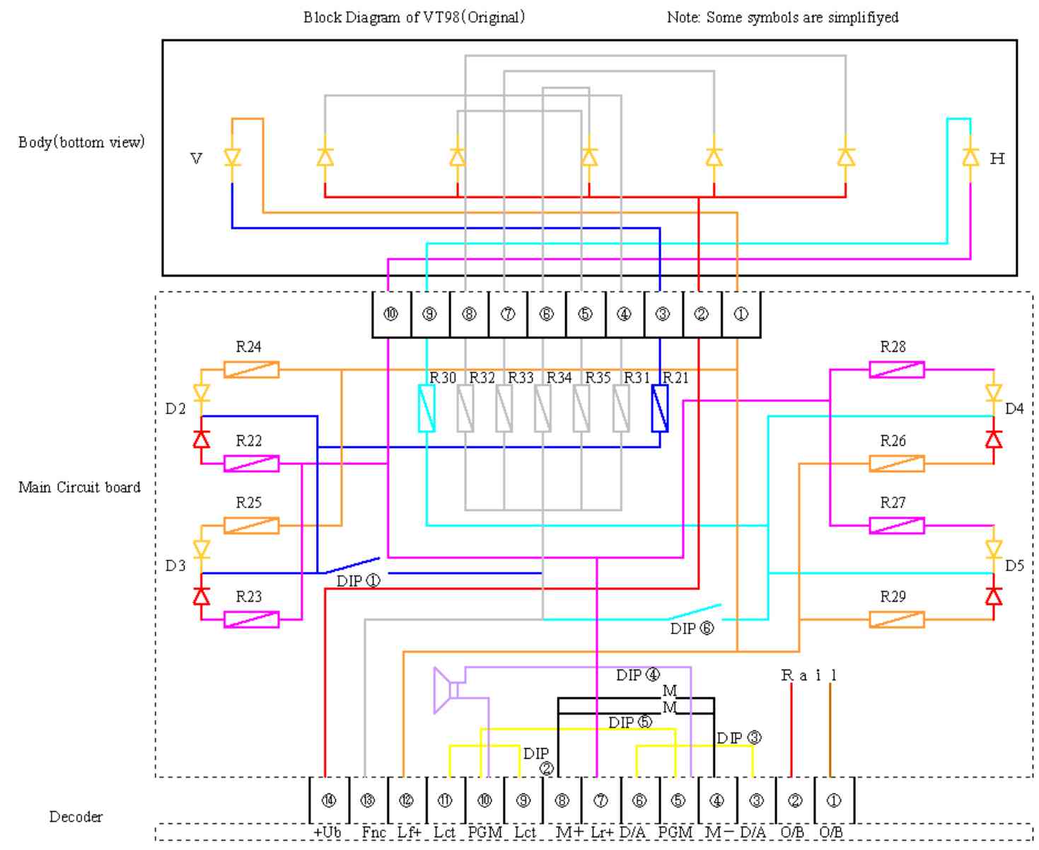 Please click on image to enlarge it.
Circuit diagram of Hübner's railbus VS98.
 Please click on image
to enlarge it.
Please click on image
to enlarge it.
Additional infos:
![]()
![]()
![]()
Copyright © 2000 by Jun Maeda / KOBE JAPAN