![]()
![]()
![]()
![]()
Installing genuine sound effect circuit to BR91.3
from märklin Premium Starter Set.
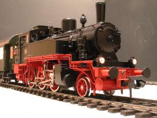
This page shows process of installing genuine sound module to BR91.3 from märklin Premium Starter Set.
Tasks of the project:
- The BR91.3 from märklin Premium Starter Set does not have sound effect however it's origin T9.3(#55910) has the circuit. So I try to add sound to my BR91.3 with spare parts for T9.3.
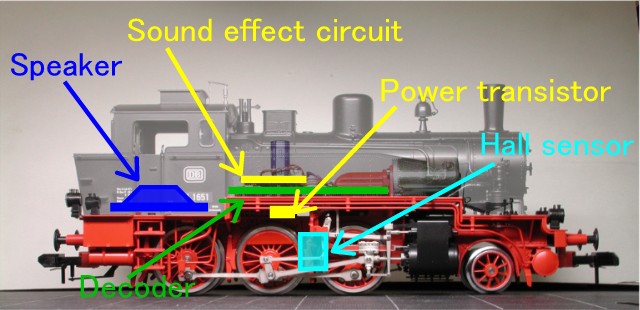
Layout of parts:
Parts needed for installing:
These spare parts are needed for installing.
Spare parts number
Description in German
Description in this document
Photo
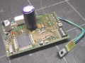
#601355
Geräusch-Elektronik
Sound effect circuit
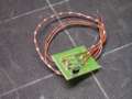
#602178
Leiterplatte Impulsgeber
Hall Sensor
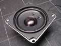
#602168
Lautsprecher
Speaker
Where are the fixing screws for upper block of cab?
It is not difficult procedure to disassemble the loco, but two essential screws are hidden.
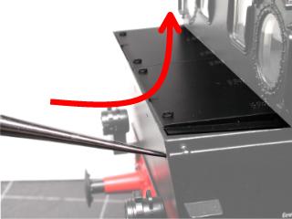
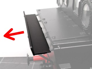
1. Pull off a 'tender step board' to rear.
2. Push up a 'coal bunker cover' from fixing hole for pin of 'tender step board' by 'L' shape fine pin.
8888II use a metal dentist's tooth pick.
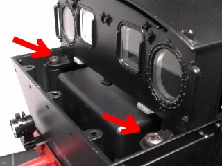
3. Then you can access to two fixing screws for upper block of cab.
Installation:
1. Carefully put off all of wires from decoder circuit board.
2. Unscrew four small screws fixing decoder circuit board and take off the circuit.
3. Remove the running gear cover on under side of frame.
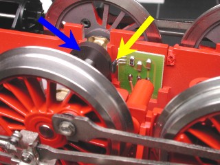
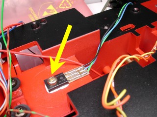
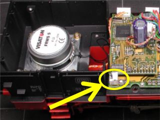
4. Install Hall sensor
The place is slot next to axle with magnet.
Blue arrow is pointing magnet on axle.
Yellow arrow is pointing hall sensor.
Three wires must be pull up to upper surface of main frame.5. Back the running gear cover to it's place.
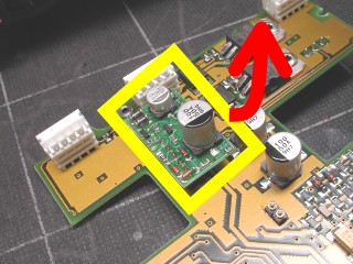
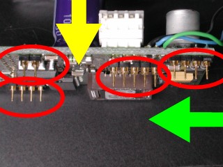
6. Take off small 'Egg timer' circuit board on decoder carefully.
DO NOT bend / break pins under side of the circuit!!!
7. Check the pins of #601355 sound effect circuit correctly right angle to circuit board.
The pins might be bent by pressure during travel to your home!
Check them not only direction of yellow arrow, but also of green arrow.
If there are any bent pin, unbend it by fine pliers with carefully.
8. Insert pins of sound effect circuit to pin header of decoder circuit board carefully.
DO NOT bend / break pins under side of the circuit!!!
9.Fix power transistor of sound effect circuit
The place is upper surface of under frame.
There are no thread groove in frame of original product. So you must use self-tap screw or cut a thread by tap to fix the transistor.
The transistor must insulated from frame. Do not peel red paint. Or for more good insulation use mica sheet etc.
I applied a little silicon grease for radiation (not rubbing grease) between transistor and frame.10. Fix back decoder circuit board with sound effect circuit by four small screws.
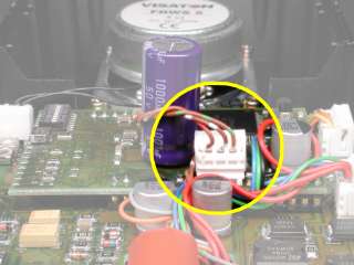
11. Connect three wires from Hall sensor circuit board to sound effect circuit.
See here for color code of wire and the terminal must be connect.
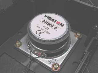
12. Unscrew the two screws fixing speaker housing and under block of cab.
13. Fix the speaker by four fixing holes on corner of speaker unit.
There are no thread groove in base of original product. So you must use self-tap screw or cut a thread by tap to fix the speaker.
The two black wires from speaker unit must draw to forward direction.14. Connect two black wires from speaker to terminal on decoder.
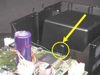
15. Fix back speaker housing and under block of cab.
The speaker hausing has small slit for avoid wires from speaker on one of the four edges pointed by yellow arrow.
Set correctly the slit and wires.
16. Connect back all wires to entire terminals. If you forget witch wire to be connecting to witch terminal -> see here.
17. Check all over your loco and confirm no problem exist such as short circuit, miss connection of wires etc..
18. Put the loco to powered rail now the sound can be hear!
![]()
![]()
![]()
Copyright © 2001 by Jun Maeda / KOBE JAPAN