


BR140(#54213)
with c95 decoder and #56560 sound effect circuit.
- This page shows changing the
decoder to conventional Gauge 1 decoder c95 and
installing #56560 sound effect circuit for BR140 two
motor electric locomotive.
- More detailed information(electric
circuit chart etc.) coming in future.
Tasks of the project:
- Change the decoder to conventional
Gauge 1 decoder c95 to get more good running character.
- Install #56560 sound effect
circuit for the whistle(only high pitch horn is used).
- No drilling, cutout for original
body or chassis.
- Install must be done without
change of exterior, include cab interior(=what you see
must not change).
- No function must be
deleted(headlight control etc.).
- Stability for daily operation and
play with RC(radio controled) vehicles.
- No modification in c95, #56560,
original lighting unit.
Original arrangements of #54213
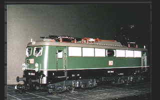
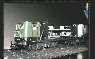
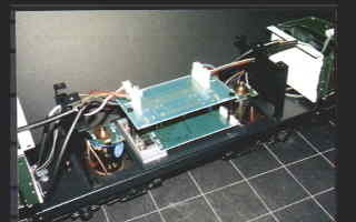
Points:
- The original circuit board(Delta)
already have 10 pin connector for #56560(common parts
with F7?). It can activate the sound only put #56560
circuit into the connector and controled by reed switch
or conventional switches(simply short the two pair of
switch connector pin on Delta PCB). The engine sound is
always 'ON', 'horn' and 'high/low pitch(for F7 bell) are
switchable(not remote controled).
- Running character of the original
decoder is as bad as other MAXI-Delta decoder, e.g. no
slow running character, no acceleration control, no road
compensation control etc..
- Head/tail light control circuit is
very differ from conventional gauge 1 loco or
conventional MAXI.(->see front/rear light control
interface relay circuit for c95 or c95/2 to MAXI loco
with LED head/tail lights(sorry, under construction).
- All the electric equipment except
motor and lights should be exchange for achieve my tasks.
All equipments are removed.
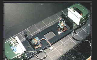
Points:
- An opening on center of the
chassis is originally for address setting DIP switches,
but it will be act as opening for speaker in new
configuration.
- New chassis for hold all
electronics equipment is needed.
Details:
<Speaker / Acoustics>
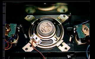
Points:
- There is a large space for the
speaker in this loco, the original speaker comes with
#56560 sound circuit can be installed.
- The speaker is firmly fixed by
four steel fittings.
- Sound comes out from opening on
floor. Whole locomotive body acts as large capacity
enclosure. No resonance dumping is needed.
<Electronics Chassis>
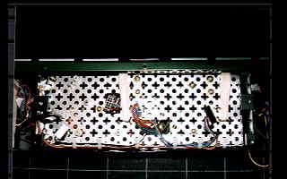
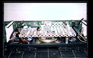
Points:
- Electronics Chassis is made from
punched aluminium plate.
- To avoid interference for sound
resonance and no minimization of enclosure capacity, the
plate should be 'punched'.
- Four corner of the plate bended to
strengthen the chassis.
<Head/tail light interface>
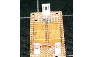
Points:
- For convert the difference of
head/tail light system between original and c95, I made
an interface circuit board.
- It has 3-pin inputs(Lf , +U, Lr)
and two pair of 2-pin outputs(each for #1 and #2
head/tail lights).
- This circuit exists to avoid
complicated re-wire on original head/tail lights unit.
- Please refer here for detail of this circuit.
<c95 or c95/2?>
At first, I consider c95/2 is best
decoder since this locomotive has two motors. But due to the less
current consumption of the motors, it seems to be feedback
control for load compensation does not works perfectly.
Comparison of c95 and c95/2(for reference original DELTA and 2x#60955):
Decoder
|
Load comp.
|
Slow running
|
Accel. cont.
|
Overheat
|
functions
|
org.DELTA
|
No
function
|
N.G.
|
No
function
|
No problem
|
No
function
|
c95
|
O.K.
|
O.K.
|
O.K.
|
No
Problem
|
4
|
c95/2
|
N.G.
|
N.G.
|
O.K.
|
No problem
|
4
|
2x#60955
|
O.K.
|
O.K.
|
O.K.
|
No problem
|
2
|
According to this result, I chose c95 for this
unit.
2x#60955(in same address settings) also
works fine. It will be a good choice for any other application.
But in this case f3 and f4 cannot be available(but with 'shunting
mode' by turn on f4).
<How about overheat problem of
#56560?>
Almost all part of MAXI BR140 made of
steel or cast metal and has enough inner capacity. So the loco
has good radiation character itself. During bench test there are
no thermal problem.
<Final fitting>
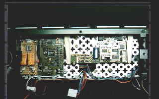
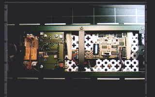
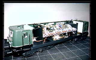
Points:
- All the electronics equipments are
fitted on electronics chassis.
- (from left to right:) Head/tail
light interface ~ #56560 sound unit ~ #6095 c95 decoder.
- c95 decoder fixed by printed
circuit card holder.
- All the pot and DIP switches on
#56560 and c95 set in upward, so adjustment can be made
only open the roofs.
- All wire harness has nylon
connector for easy maintenance.
Conclusion:
- All the tasks I enforced for
myself has achieved.
- MAXI loco can be get higher
running potential by change a decoder.
- A highpitch horn of BR218 is used
in place of whistle, but this gives me more than
"better than nothing" effect. It's very
attractive!


Copyright © 2000 by Jun Maeda / KOBE JAPAN


