![]()
![]()
![]()
![]()
Front/rear light control interface circuit
for
c95 series decoder and MAXI loco with LED head/tail lights
Because of difference of circuit system between MAXI and standard gauge 1 locos, the c95 series (#6095, #60952, #60955) decoders cannot directly control head/tail lights of MAXI loco (example E10/E40).
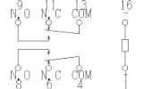
Circuit diagram:
This diagram shows 'Lf=off / Lr=off' status.
How does it works?
This diagram shows 'Lf=on' status.
This diagram shows 'Lr=on' status.
This diagram shows 'Lf=on / Lr=on' status.
- This status never occur in normal operation.
- Series relay contact protects LED and output transistor of decoder from damage by short circuit.
Actual Unit for E40
This is a sample circuit for my E40. Please refer here too.
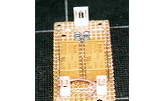
PCB layout diagram
Please click on image to enlarge it.
Bottom view of relay.
Relay: Matsushita(NAiS) :DS2E-M-DC12V


Copyright © 2001 by Jun Maeda / KOBE JAPAN